Laboratory web page:
Laboratori Nazionali del Sud, LNS (external link)
Kore University of Enna (external link)
The Physical Chemistry Techniques Department of Laboratori Nazionali del Sud (LNS) of INFN in Catania aims to be a point of reference for chemical and chemical-physical problems. It has over thirty years of experience in preparing targets for physics experiments. Among the various tasks, it deals with the preparation of the strippers for the LNS accelerator machines, a Tandem VandeGraaf and a Superconducting Cyclotron, and the cathodes for the sputtering negative ion sources. In addition, it develops and carries out chemical treatments and special chemical cleaning. Users are both researchers and colleagues from other departments or services.
Target Realization
The production of the targets is divided into the following phases:
Phase 1: Exploration and Prototyping. Starting from the requirements that must be met for the experiment, plates are studied and produced as a prototype. The techniques for obtaining the films can be classified as chemical, mechanical and physical. In table 1 the proper technique used at LNS is associated to the desired target to be obtained.
| Film | Backing | Method | |
| Ag | self supp. | evaporation/rolling | |
| Al | C/self supp. | evaporation | |
| Au | self supp. | evaporation | |
| 10-11B | self supp. | evaporation | |
| 116Cd | C/self supp. | evaporation | |
| CaF2 | C | evaporation | |
| C | Self supp. | evaporation | |
| 52Cr | self supp. | evaporation | |
| CrF3 | C | evaporation | |
| 63Cu | Kapton/self supp. | evaporation/rolling | |
| 74Ge | self supp. | evaporation | |
| K39Cl | Au | evaporation | |
| 6-7LiF | C/Mylar/glass | evaporation/chemical deposition | |
| 6LiH | C/Al | evaporation | |
| 6Li2O | C | evaporation | |
| 56Fe | self supp. | evaporation | |
| 24Mg | Au/self supp. | evaporation /rolling | |
| 92-100Mo | self supp. | evaporation /rolling | |
| 58-60-64Ni | self supp. | evaporation/rolling | |
| Nb | self supp. | rolling | |
| Polyethylene | self supp. | Solvent casting | |
| Deuterated Polyethylene | self supp. | Solvent casting | |
| 208Pb | C | evaporation | |
| Rh | self supp. | rolling | |
| Sc | C/self supp. | evaporation /rolling | |
| Sb2S3 | C/Au | evaporation | |
| Si | C/self supp. | evaporation | |
| 112-116-119-120-124Sn | self supp. | evaporation | |
| SnO2 | C | evaporation | |
| Teflon | self supp | evaporation | |
| 48Ti | self supp. | evaporation | |
| Ta | C/self supp. | evaporation/rolling | |
| V | self supp. | rolling | |
| W16-17O3 | Au/C | evaporation | |
| Y | self supp. | rolling | |
| 64Zn | C/Au | evaporation/rolling | |
| 90-92ZrO2 | C | evaporation |
The choice of the technique to be used depends mainly on the type of compound available and on the thickness to be achieved [Mug87][Ses12]. Very thin films, less than 1 µm, are produced using the PVD (Physical Vapor Deposition) technique [GR84]. The material to be deposited is heated to a high temperature in a vacuum chamber where, evaporating from the heated source, it condenses on a suitable substrate. The simplest system to evaporate is the one in which the material to be volatilized is heated, exploiting the Joule effect of an electrical resistance crossed by a current. The most used thermal sources are those with refractory metal elements such as W, Ta or Mo in filaments, or boats to contain the evaporant. Some metals or compounds can form alloys or react with the materials that make up the thermal sources. In these cases the electron gun is used. The material to be evaporated is placed inside a water-cooled copper crucible in a high vacuum chamber. A suitable electromagnetic field conveys the beam on the material placed in the crucible. The beam provides the amount of energy needed to melt and evaporate the material.
In many cases the thickness of the film material is too thin to be mechanically processed. In these cases it must be deposited on a slide coated with a suitable soluble release agent. By dissolving the release agent in a liquid solvent, the film floats on the surface of the solvent and can be picked up with a frame. In this way self-supporting films are obtained (fig. 1 and 2).
(Credit: INFN-LNS)
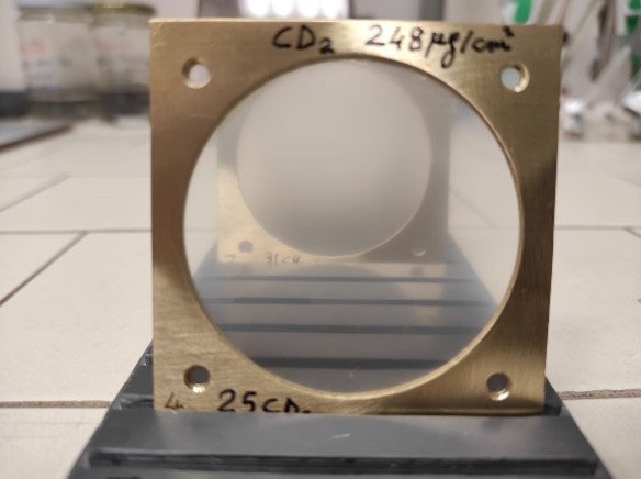
(Credit: INFN-LNS)
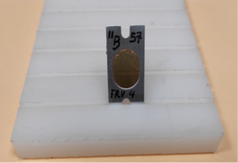
In cases where it is impossible to obtain self-supporting targets, the material is evaporated directly onto a suitable support material such as, for example, a thin film of carbon (fig. 3), gold or aluminum (fig. 4).
(Credit: INFN-LNS)
(Credit: INFN-LNS)
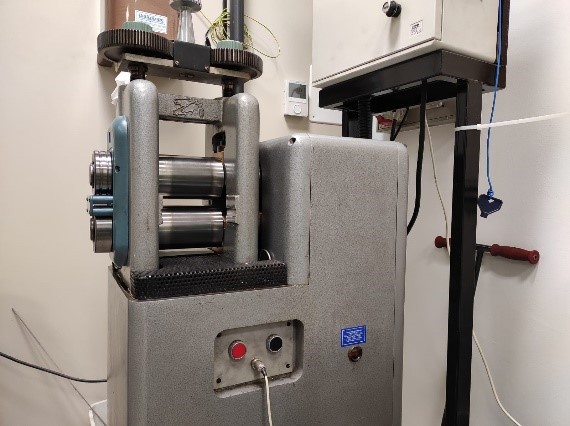
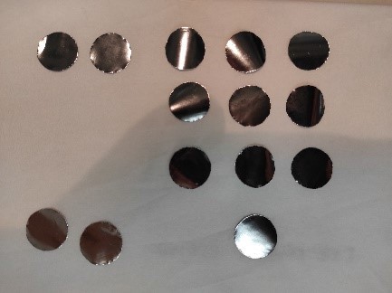
In the case of metal targets with thicknesses greater than 1 µm, cold lamination is used [Tho75]. The metal foil is progressively thinned with a cold rolling mill (fig. 5) in a sandwich process between two hardened stainless steel plates until it reaches the desired thickness (fig.6).
(Credit: INFN-LNS)
(Credit: INFN-LNS)
During the realization of the prototype the natural material is used, not enriched.
Phase 2: Finding the material. Having developed the procedure for the realization of the targets, we take care of the purchase of the isotope of the required chemical element. The material to be used for making the film must have the highest possible chemical purity, higher than 99.99 %, to prevent interference from unwanted elements in the target. Furthermore, it must satisfy the condition of higher isotopic purity. In this context we refer to the relationship between the isotope of interest and the other isotopes of the same element. Today the availability of isotopes is severely limited due to the small number of producers. In some cases, a compromise must be found between the high cost of the necessary isotope and the percentage of enrichment that can be found on the market.
Phase 3: Production. Once the method has been developed and the necessary material has been found, we proceed with the creation of the required plates.
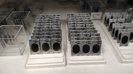
Characterization and size of the targets. Each plate produced in the laboratory is characterized with respect to its surface density, its thickness, its uniformity. During evaporation, the thickness of the deposited material is continuously monitored using a quartz micro-balance (Quartz Crystal Monitor), placed inside the evaporation chamber. It is an extremely mass-sensitive apparatus that measures variations at the level of the nano-gram and micro-gram of mass per unit area. The heart of the technology is a quartz disc. Quartz is a piezoelectric material that can be made to oscillate at a defined frequency by applying a suitable voltage. The frequency of oscillation is affected by the addition of small amounts of mass on its surface. This frequency variation, being dependent on the amount of matter deposited, provides the evaporation rate and the amount deposited over time. To have a more accurate measurement on the single plate or a thickness uniformity measurement, again for ultra-thin films, we proceed to a further characterization. It is known that when a beam of alpha particles of well-defined energy crosses a film, they lose an amount of energy that is directly proportional to the thickness of the material passed through [Tho75].
(Credit: INFN-LNS)
(Credit: INFN-LNS)
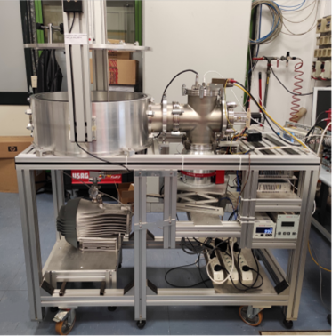
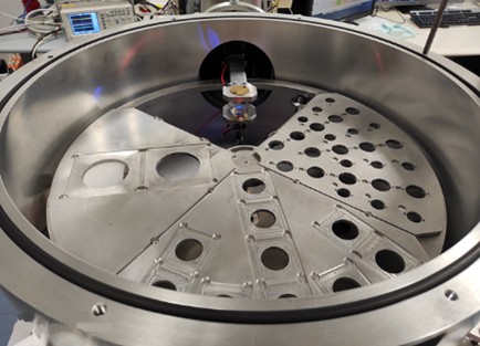
Moreover, a machine determining target thickness by measuring alpha particles energy loss has been created at LNS (fig. 7 and 8). It is made by a scattering chamber with a high vacuum system, a 241Am α source, a detector and an electronic system for the acquisition and amplification of signals, the mechanics for samples handling. A software has been developed for the control of the machine which autonomously performs the measurement of a sequence of targets (see fig. 9).

(Credit: INFN-LNS)
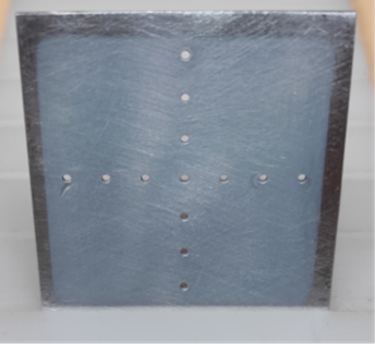
It is also able to provide the uniformity of the targets, determining the thickness on different points of the surface of the same target. When the thickness of the film is greater than about one micrometer and can be handled without breaking, its surface is measured and the weight is determined with an analytical balance with five decimal places. From the ratio between its weight and its surface, the surface density in µg/cm2is obtained and from this, knowing the density of the material, it is possible to calculate the thickness.
Laboratory Equipment
- 2 PVD evaporators with thermal sources and electron beam (figures 10 and 11);
- 1 technical scale;
- 1 analytical balance with five decimal digits (fig. 12);
- 1 rolling mill (fig. 5);
- 1 automatic thickness measuring machine (fig. 7 and 8);
- 1 chemical hood.
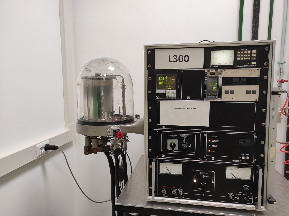
(Credit: INFN-LNS)
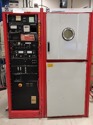
(Credit: INFN-LNS)
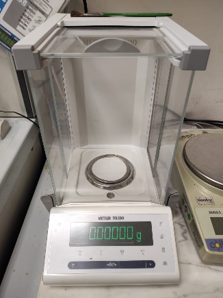
(Credit: INFN-LNS)
Noble gases targets
An ion implantation facility is going to be set up at LNS for the creation of solid targets of noble elements with high enrichments.
This will be done thanks to Nestor (fig. 13) [Maz22], a recently installed ECR ion source of noble elements, to be coupled to the LNS Tandem pre-acceleration system.
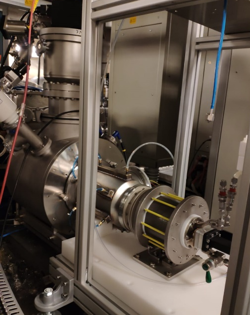
(Credit: INFN-LNS)
When a noble element should be used in an experiment, this is generally involved as a gas target, being very tough to create solid compounds. However, this is not always a satisfying solution, because of the huge angular spread and energy loss spread in the gas targets, which cannot fit the experimental needs. For this reason, noble elements solid targets are often required to be created, in the most cases with implantation, then challenging with a greater as possible enrichment.
Helium and Neon will be the elements considered for implantation onto a host material, yet to be found as the best for this purpose among a series of elements to be tested. These targets obtained will be tested to follow their stability under beam bombardment.
References
[Mug87] Deposition techniques for the preparation of thin film nuclear targets. A.H.F. Muggleton Vacuum Technology Application and Ion Physics. ANU-P/965 July 1987.
[Ses12] Handbook of thin film deposition. Processes and Technology. Krishna Seshan, Second Edition
[GR84] Preparazione di Films sottili per esperimenti di fisica nucleare con acceleratori di particelle. Annemarie Geuer-Richter, Institut für Kernphysik der Universität zu Koln (January 1981). Translated from German by Ruggero Pengo LNL, INFN/TC-84/1 4 January 1984.
[Tho75] D.M. Thompson, Proc. 4th Int. Conf. Nuclear Target Development Soc., Argonne, Illinois, USA, ANL/FHY/MSD-76-1,44 (1975).
[FWS+17] Improved technique for preparation of deuterated-polyethylene targets M. Febbraro, D. Walter, S.C. Shadrick, S.D. Pain, K.A. Chipps, C. Thornsberry, E. Lesser Nuclear Instruments and Methods in Physics Research B 410 (2017) 53-59.
[Maz22] Design and first operations of a ECR based He source at INFN-LNS, M. Mazzaglia et al, J. Phys.: Conf. Ser. 2244 012037 (2022)